Nuclear Power
A Zero Emission Clean Energy SourceNuclear power is the second largest source of low-carbon electricity globally. And to tackle the threat of climate change, continued research and development into nuclear technology is crucial. This will help ensure nations reach net-zero carbon emission by 2050.
Nuclear power is a zero-emission clean energy source ideally suited to complement other green energy technologies such as solar and wind. And with new advancements in efficiency and safety, it remains a viable option for a greener future.
Materials characterization is essential
When it comes to nuclear power generation, optimizing the performance of certain materials is a must. For example, graphite is used in reactor cores - it moderates the reaction and can shut it down when necessary. And the microstructure of graphite is what gives the material the properties and performance necessary to perform this important function. Characteristics such as tortuosity, pore shape and anisotropy, and connectivity can drastically influence the material’s behavior.
But one of the challenges is that this microstructure is hard to characterize. The material is highly multiscale and heterogeneous, consisting of repeating domains with different microstructural features. The porosity, hardness, and composition of nuclear graphite also presents a problem, as it makes FIB preparation difficult and slow.
Advanced microscopy tools can help
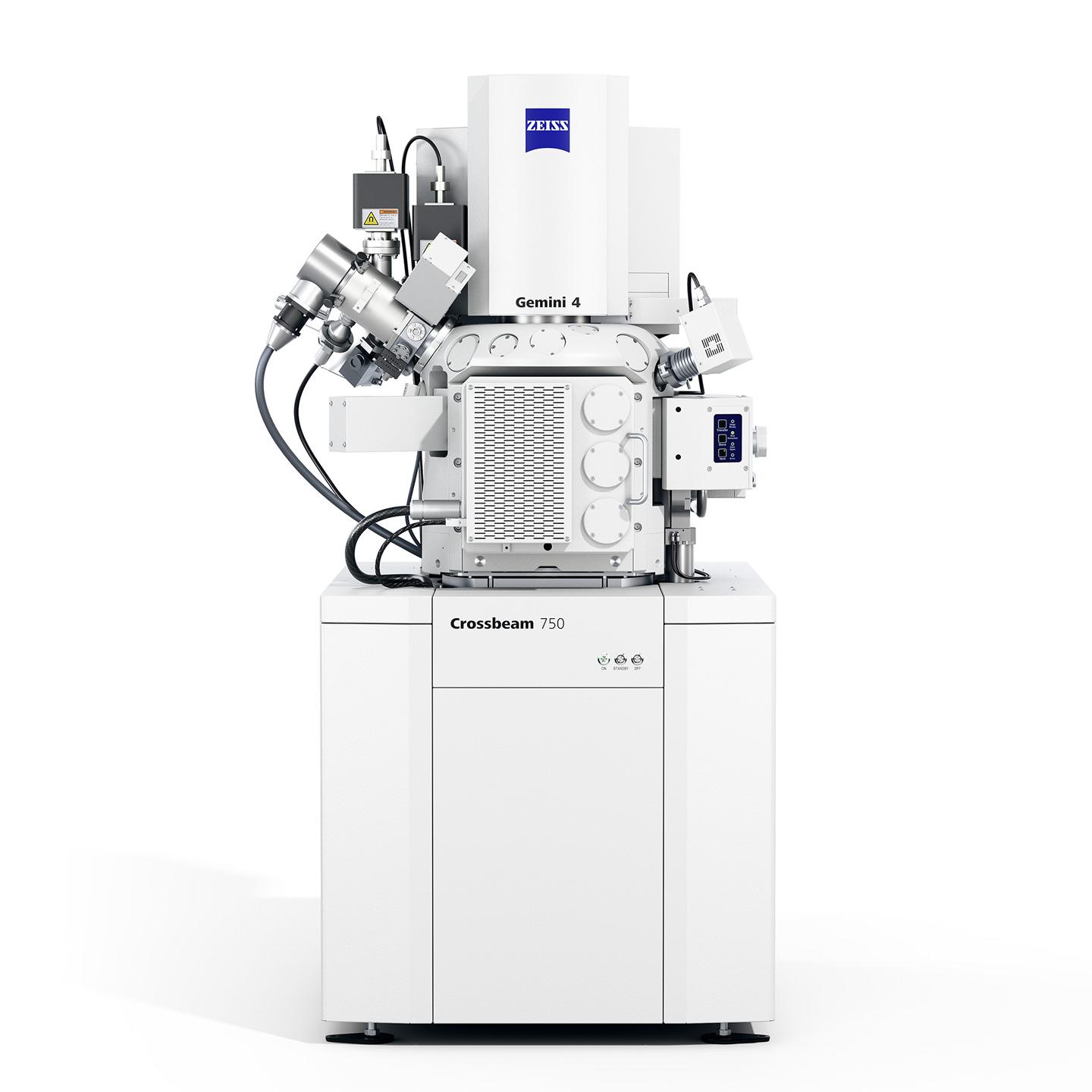
ZEISS offers several solutions that can help improve the characterization of nuclear materials - paving the way for a greener future. The LaserFIB, a ZEISS FIB-SEM combined with a laser, allows scientists to perform fast, high-throughput sample prep for high-resolution imaging. Correlative analysis with X-ray microscopy is also possible.
Your Next Step
Find out more about ZEISS’ analysis tools for nuclear materials.


 particle cracks initiate at top and bottom of the particle. (Right) brittle failure of the coating layers occurs.")
 particle cracks initiate at top and bottom of the particle. (Right) brittle failure of the coating layers occurs.")