ZEISS Correlative Cryo Workflow
TEM Lamella Preparation and Volume Imaging under Cryogenic ConditionsZEISS Correlative Cryo Workflow connects widefield, laser scanning, and focused ion beam scanning electron microscopy in a seamless and easy-to-use procedure. The solution provides hardware and software optimized for the needs of correlative cryogenic workflows, from localization of fluorescent macromolecules to high-contrast volume imaging and on-grid lamella thinning for cryo electron tomography.
Imaging the Near-To-Native State


A Simplified Workflow to Help You Focus On Your Research
With ZEISS Correlative Cryo Workflow, you master the challenging combination of different imaging modalities under cryo conditions. The workflow solution connects light and electron microscopy, enabling volume imaging and efficient production of TEM lamellae. Dedicated accessories simplify the workflow and facilitate a safe transfer of cryo samples between the microscopes. Data management is assured by ZEN Connect, which keeps your data in context throughout the workflow. A series of processing tools help you enhance the imaging results.
")
")
 Sample courtesy M. Pilhofer, ETH Zürich, Switzerland")
 Sample courtesy M. Pilhofer, ETH Zürich, Switzerland")
Double-labelled yeast cells (CNM67-tdTomato and NUP-GFP). LSM image (left) and Crossbeam image (right).
Superior Components to Give You Best-In-Class Data Quality
Thanks to cryo-compatible objectives and the high sensitivity of the Airyscan detector, ZEISS LSM systems enable you to detect proteins and cellular structures at high resolution while gentle illumination and constant low temperatures prevent your samples from devitrification. The ZEISS Crossbeam FIB-SEM lets you enjoy high-contrast volumetric imaging – even without heavy metal staining applied to your samples. Both modalities provide valuable functional and structural information that can give you a thorough understanding of ultrastructure, whether or not you follow up with TEM studies.
Caption: Double-labelled yeast cells (CNM67-tdTomato and NUP-GFP). LSM image (left) and Crossbeam image (right). Sample courtesy M. Pilhofer, ETH Zürich, Switzerland


Multipurpose Solutions to Maintain Your Imaging Facility’s Productivity
Unlike other solutions, the ZEISS microscopes involved in the workflow can be used not only for cryogenic microscopy, but also for room temperature applications, which is particularly advantageous when the microscopes are not being fully utilized for cryogenic experiments. Converting the instruments from cryogenic to room temperature usage is done quickly and doesn’t require technical expertise. This flexibility gives users more time for their experiments. Imaging facilities benefit from better utilization and a faster return on investment.
ZEISS Correlative Cryo Workflow at a Glance


")
")
")
")
Solution Overview


ZEISS Cryo Accessory Kit


ZEISS Cryo Accessory Kit
ZEISS Cryo Accessory Kit
ZEISS Correlative Cryo Workflow allows the use of various sample carriers. Whether you use TEM grids, AutoGrid, sapphire discs or HPF planchets, you can count on the Cryo Accessory Kit to enable easy loading, transfer and storage of your sample. A collection of items and tools supports safe sample handling throughout the entire workflow. The components are compatible with:
- Linkam CMS196V4 cryo-correlative microscopy stage
- Quorum PP3010Z cryo system


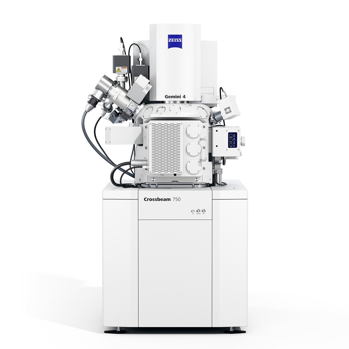
ZEISS Crossbeam: Rotatable cryo substage


ZEISS Crossbeam: Rotatable cryo substage
Easy Sample Transfer and Safe Sample Handling Inside ZEISS Crossbeam
ZEISS Correlative Cryo Workflow comes with Quorum PP3010Z, a highly automated, easy to use, gas-cooled cryo preparation system.
- The turbo-molecular pumped cryo preparation chamber includes tools for controlled, automatic sublimation and sputter coating.
- From the cryo preparation chamber connected directly to the ZEISS Crossbeam chamber, the vitrified sample is transferred onto a highly stable cold stage for imaging and milling.
- Cold trapping in the cryo preparation chamber and Crossbeam chamber protects the sample from ice contamination.
- Continuous cooling for at least 24 hours is ensured by the CHE3010 off-column cooling system.
- All Quorum cryo components are controlled by the Prepdek® workstation, including the vacuum storage tube for the cryo transfer device and the TEM prep slusher for the ZEISS loading station.
The Most Reliable Imaging Modalities Combined


Correlative cryo dataset in ZEISS ZEN Connect
Correlative cryo dataset in ZEISS ZEN Connect
Keeping Everything Together: A Well-Aligned Software Package
To ensure a streamlined correlative cryo workflow and that the various components work together seamlessly, the software platforms involved were extended to include cryo-specific functions. Additional software modules have been developed to address the challenges arising from correlative cryogenic microscopy.
- ZEN
- ZEN Connect Toolkit
- ZEN EM Processing Toolbox
- SmartSEM and SmartFIB
- Cryo Drift Reduction


 as well as several mitochondria.")
 as well as several mitochondria.")
 and cross-sectioned microtubules outside the nuclear membrane (bottom).")
 and cross-sectioned microtubules outside the nuclear membrane (bottom).")
 and cross-sectioned microtubules outside the nuclear membrane (bottom).")
 and cross-sectioned microtubules outside the nuclear membrane (bottom).")
Longitudinally sectioned spindle pole body within the nuclear membrane (top) and cross-sectioned microtubules outside the nuclear membrane (bottom). Image step size of the acquired stack: 50 nm
Longitudinally sectioned spindle pole body within the nuclear membrane (top) and cross-sectioned microtubules outside the nuclear membrane (bottom). Image step size of the acquired stack: 50 nm


 or the genome in different mitotic phases (*cell in metaphase, # cell in telophase).")
 or the genome in different mitotic phases (*cell in metaphase, # cell in telophase).")


 or the genome in different mitotic phases (*cell in metaphase, # cell in telophase).")
 or the genome in different mitotic phases (*cell in metaphase, # cell in telophase).")
 or the genome in different mitotic phases (*cell in metaphase, # cell in telophase).")
 or the genome in different mitotic phases (*cell in metaphase, # cell in telophase).")
Related Applications


Cybersecurity at ZEISS Microscopy
As digitalization advances in microscopy, so do the complexities of cybersecurity. ZEISS Microscopy is committed to proactively securing our technologies and protecting our customers. Our Cybersecurity and Data Privacy Governance Program goes beyond traditional security—it also encompasses Responsible AI and Open Source Software (FOSS) governance.